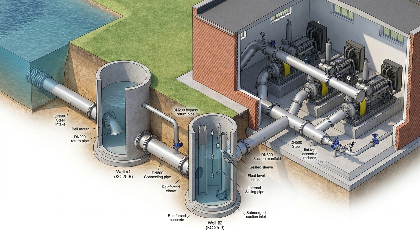


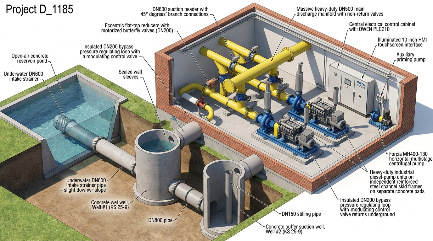

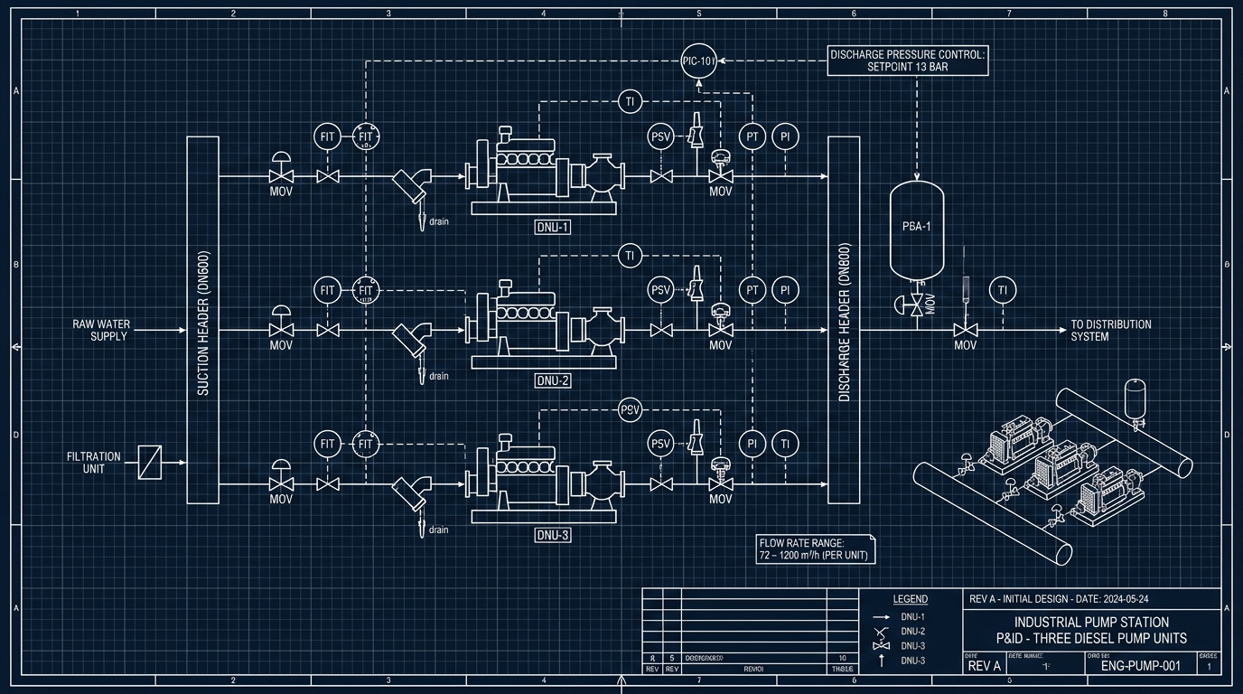



3D isometric engineering cutaway diagram and technical visualization of an industrial water intake and pumping station according to exact hydraulic layout: 1. On the far left, open water pond/reservoir with a submerged intake pipe DN600 with intake screen. 2. DN600 pipe leads straight underground into the first outdoor concrete wet well (Well #1, circular concrete chamber КС 25-9). 3. From Well #1, the connecting large pipe DN800 exits at a strict 90-degree right angle turn, running horizontally to the second overflow/buffer concrete wet well (Well #2, КС 25-9). 4. Inside Well #1, also shows the submerged DN200 bypass return pipe entering from the building with a 90-degree elbow pointed at the bottom wall. 5. From Well #2 (overflow well with internal stilling pipe and float level sensors), a direct straight DN600 suction manifold exits horizontally, penetrates through the brick pump house foundation sleeve into the indoor machinery hall. 6. Inside the pump house: DN600 suction collector splitting via 45-degree branches with flat-top eccentric reducers into 3 large diesel-driven pump units (multistage centrifugal pumps coupled to industrial diesel engines on concrete foundations), connected to a high-pressure DN500 discharge manifold and the DN200 bypass line with modulating control valve. High-precision 3D CAD/BIM cutaway rendering, clean transparent ground cutaways revealing exact underground pipe routing and 90-degree turn between wells, professional technical lighting, industrial realism.
Free to start · Generate videos and images with AI in seconds